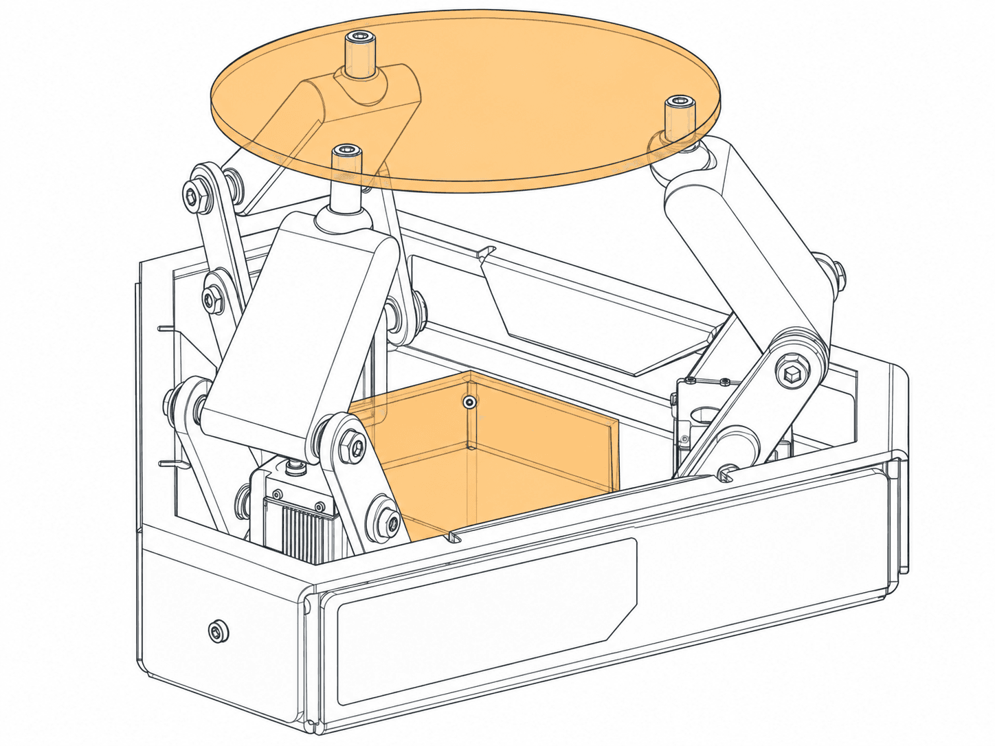
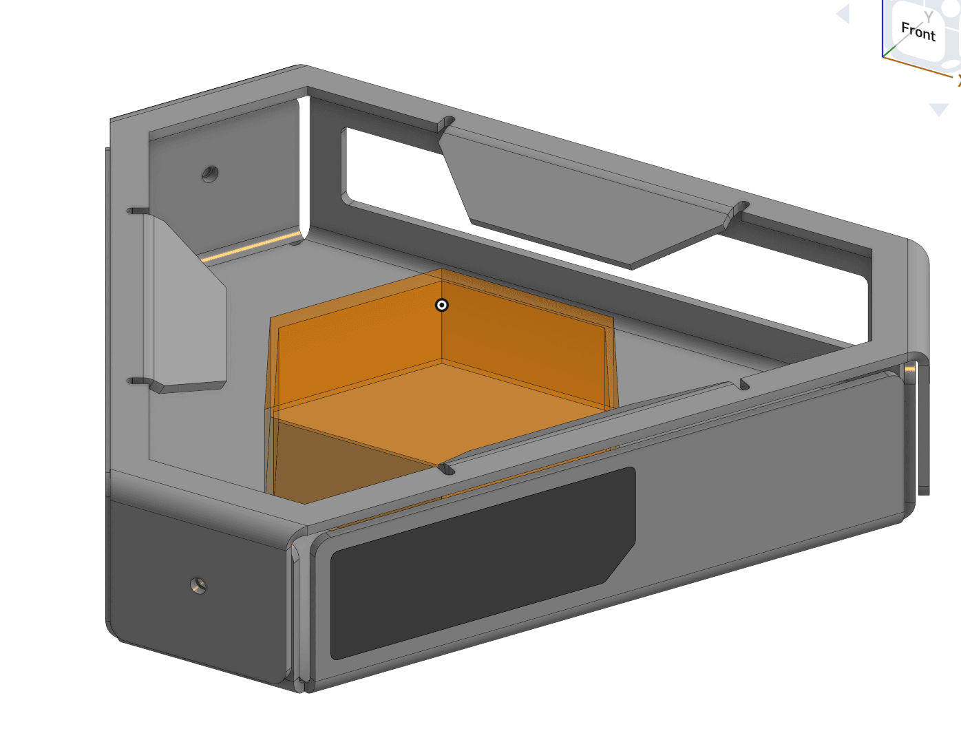
BL01 product design in Onshape. The amber plate and exposed mechanism sit above a clipped triangular enclosure.
An experiment you can actually read
A ball on a moving plate is a deceptively small problem. To keep it in place, the machine has to see where it is, decide how the plate should tilt and turn that decision into three coordinated motor angles. A delay, a loose joint or a poor calibration shows up immediately in the motion.
I designed BL01 as a desktop instrument for exploring that relationship. The aim is to balance a lightweight ball, follow simple paths and compare control choices using recorded data. I wanted the mechanics to stay visible, with a clear front for interaction and a separate area for power connections. It should feel like something you can experiment with, understand and service.
Current stage: mechanical CAD and analytical design review, September 2026. The product form and minimum mechanism are modelled. Selected CAD poses have been compared with inverse kinematics. Electronics, closed-loop operation and physical performance still need to be built and tested.
Start with the motion, then give it a body
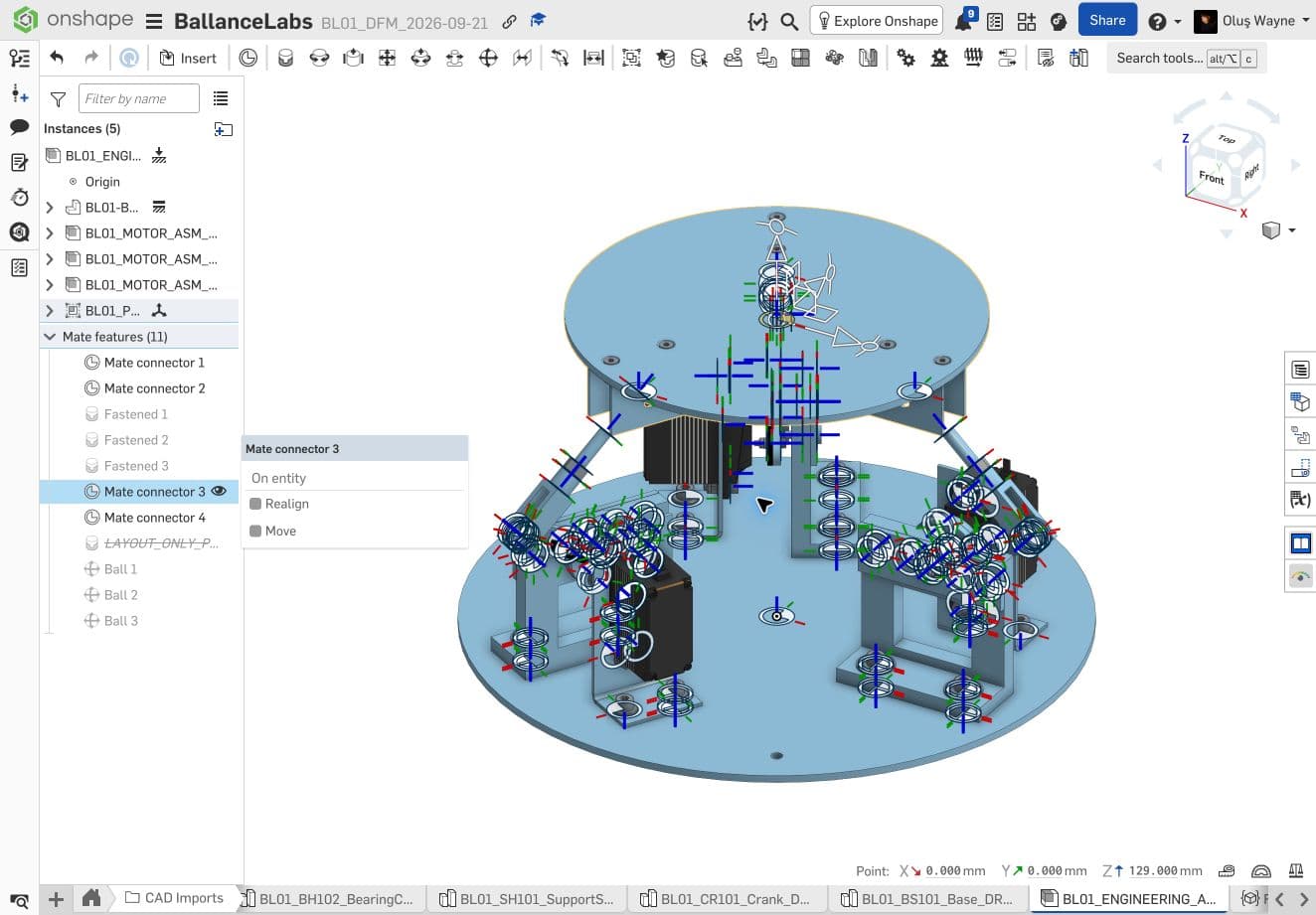
The minimum engineering assembly uses a circular base, three motor stations spaced 120° apart and a moving plate. Each motor turns a crank; an upper link connects that crank to a spherical joint on the plate. Coordinated movement changes height, while differential movement produces tilt.
This is the mechanically articulated MVP candidate, not a completed balancing prototype. Keeping the enclosure out of this assembly made the important questions easier to isolate: joint positions, required travel, motor references and assembly clearances. The engineering base and the shaped product enclosure are separate CAD configurations whose interfaces still have to be reconciled.
Minimum engineering assembly. The visible mate and axis overlays belong to the CAD inspection; this is not a photograph of a built prototype.
One set of dimensions, from calculation to CAD
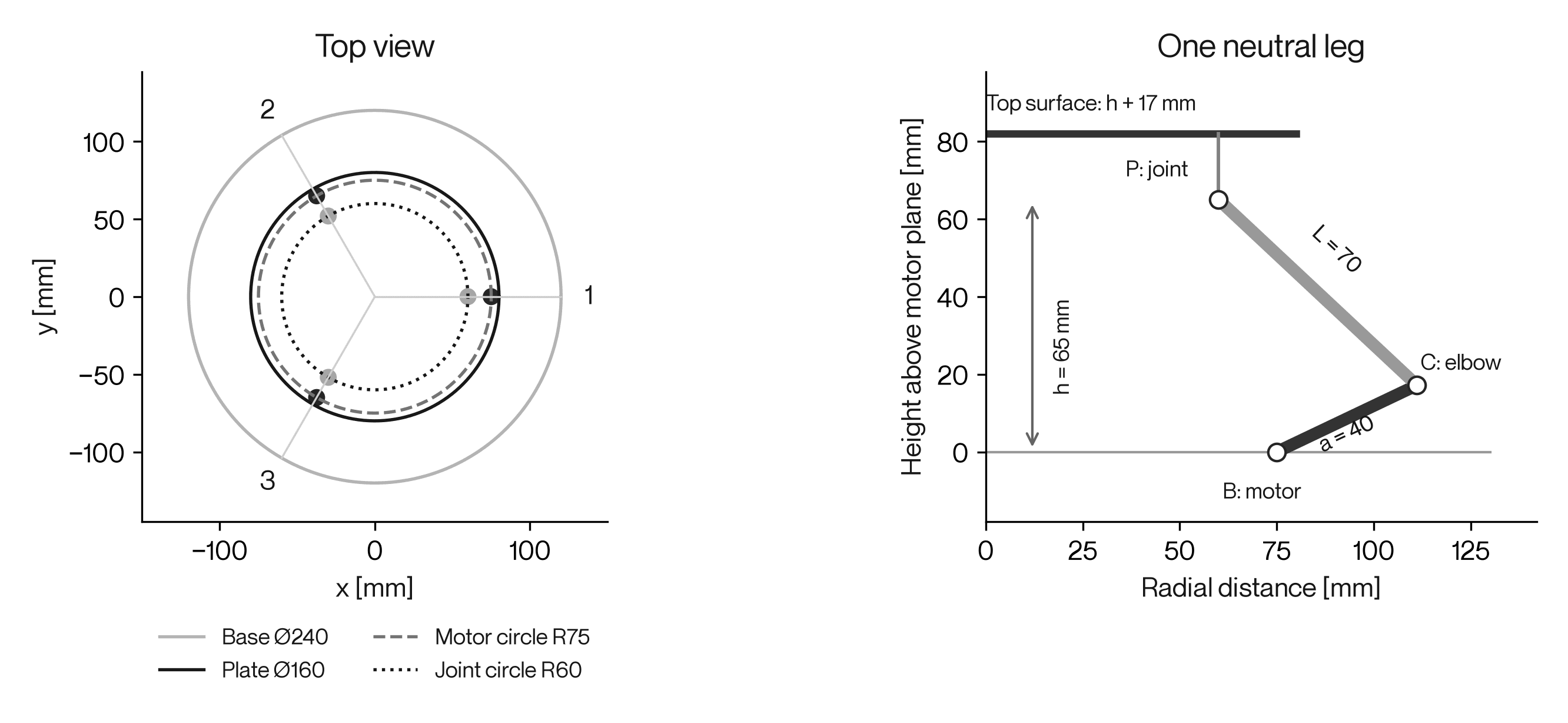
The R40 engineering candidate uses a 160 mm plate, 40 mm cranks and 70 mm upper links. Motor centres lie on a 75 mm radius; plate joints lie on a 60 mm radius. The nominal joint-plane height is 65 mm above the motor-axis plane, with a sampled height range of 60–70 mm.
For a 40 mm ball, the plate radius does not equal the usable ball-centre radius. Subtracting the 20 mm ball radius and a provisional 10 mm edge allowance leaves a 50 mm centre region. Initial path tracking is proposed on a smaller, 20 mm radius circle.
The inverse-kinematic model resolves a requested plate pose into the three crank angles. It also includes the small horizontal drift and yaw imposed by the leg-plane constraints; assuming a perfectly fixed plate centre would describe a different mechanism. At the level 65 mm pose, the analytical crank angle is approximately 25.439°. Mapping that value to an Onshape mate requires the recorded reference offset; physical servo calibration will be a separate measurement.
Analytical geometry from the R40 parameter set. Height is measured to the plate-joint plane, not the top surface.
Check the geometry before trusting the motion
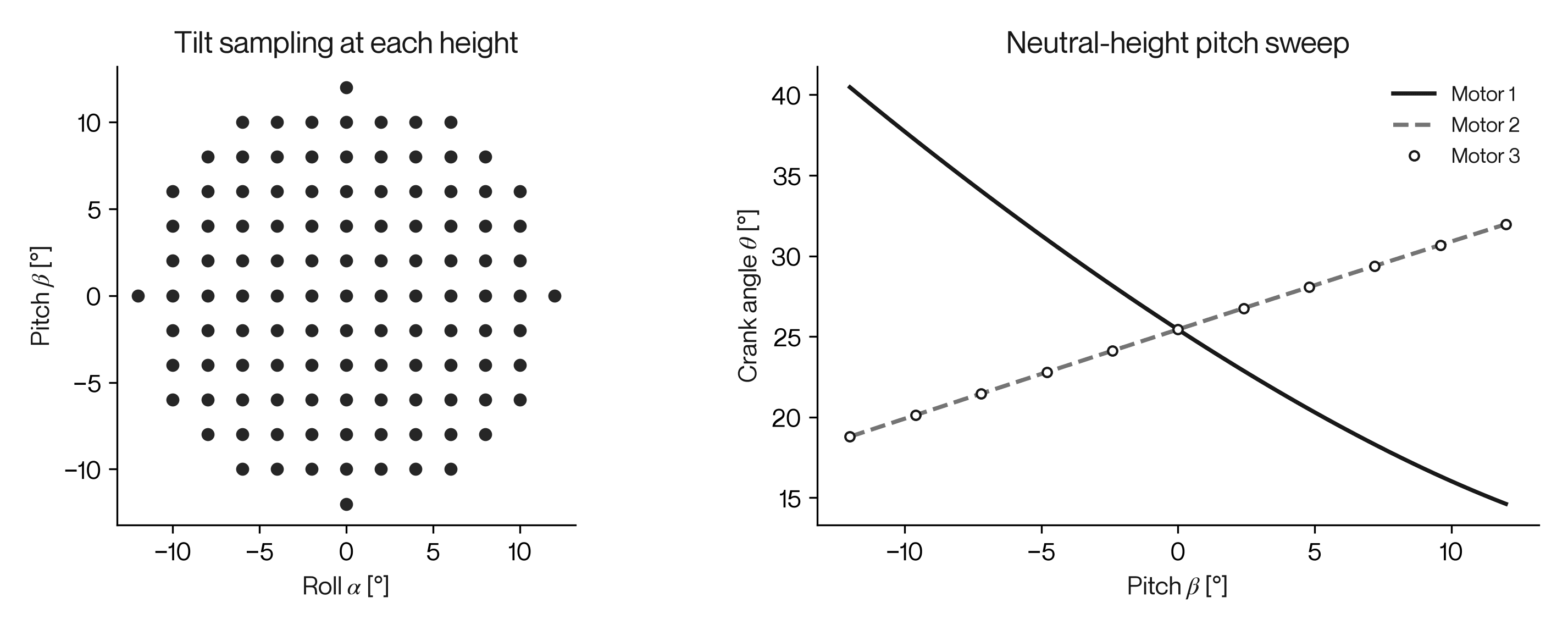
I screened 678 discrete poses across six heights, with resultant tilt limited to 12°. The sampled crank angles span approximately 8.890°–45.862°. Maximum horizontal drift is about 0.656 mm and maximum parasitic yaw is 0.560°. These are geometric model results, not measured hardware performance.
A separate comparison uses recorded Onshape joint coordinates. At a 67 mm height, 4° roll and 3° pitch, the largest difference between the analytical and displayed coordinates is 0.000436 mm—agreement within the CAD interface’s 0.001 mm rounding. That checks the coordinate model; it does not imply sub-micron manufacturing accuracy.
The remaining gates are practical: continuous collision clearance, purchased-joint articulation, threaded engagement, backlash and actuator response. The 12° sampled envelope is not the starting command limit. The first powered tests should use a much narrower tilt range, around 3°, at the nominal height.
678 sampled poses; the angle curves describe an analytical sweep, not a measured control response.
From a mechanism to an instrument
I wanted the product to feel precise and slightly futuristic without hiding how it works. Compact instruments offered more useful references than generic robot housings. The Teenage Engineering TX–6 informed the restraint and density of the interface; the Moog Mother-32 suggested clear zoning between interaction and connections; the KORG NTS-1 mkII showed how visible assembly and replaceable panels can belong to a finished object.
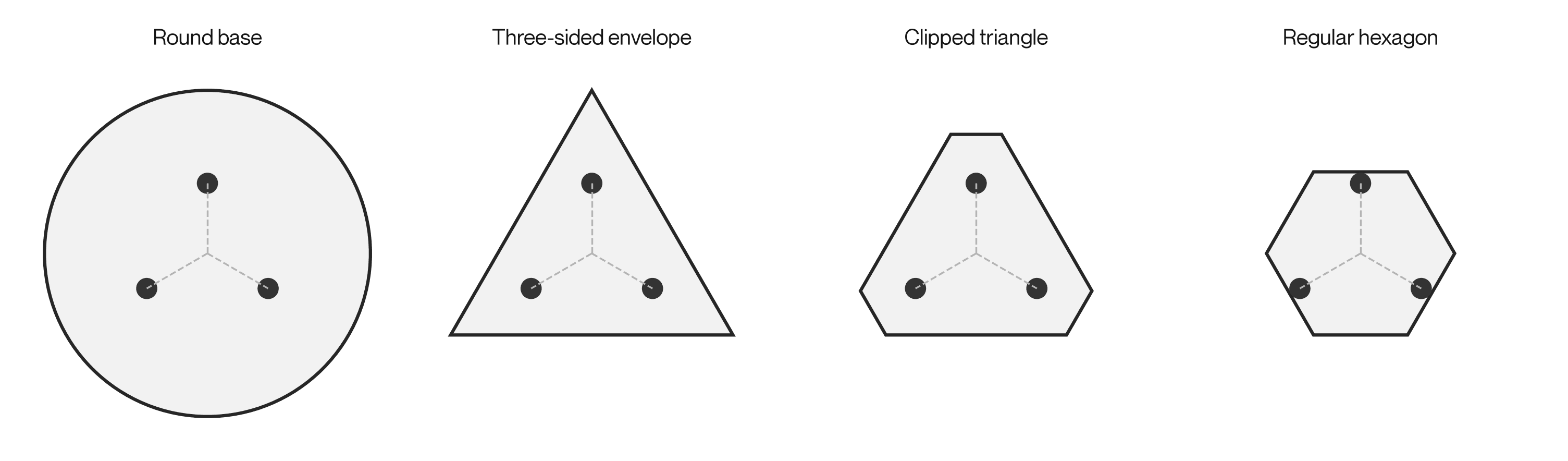
The three motor stations give the enclosure a triangular starting point. Clipping the narrow corners creates three long faces and three short corner faces. It looks almost hexagonal, but it is not a regular hexagon: the hierarchy of the triangle remains. The long faces provide room for interfaces, while the removed tips avoid committing the design to awkward corner volumes.
The form diagram is an explanation of that decision, not a measured optimisation. Motor bodies, cable bends, tools and moving links still decide how much corner can actually be removed.
The clipped triangle keeps three dominant faces. Six edges do not make it a regular hexagon.
A front for control, a rear for power
The dark inset on the front is the intended control interface. It is already part of the design, but its implementation is waiting for the electronics choices. I have reserved the interaction area without pretending that a display, buttons or indicators have already been selected.
The open rear strip has a different job: power inputs and outputs, the on/off switch, fuse access and related fittings. I planned a PLA cover that fits onto the metal chassis. Its cut-outs and fixing details will follow the selected components. That cover is also intended to support ventilation, although the airflow path and temperatures still need testing with the real electronics.
Above this lower body, the circular amber plate and exposed linkages keep the motion legible. The amber finish expresses a material direction in the product CAD; the engineering mass study uses a 3 mm aluminium plate candidate. The final material choice must account for stiffness, mass and the camera’s view of the ball.
Front: reserved control interface. Rear: power connections, switch and fuse access behind a planned fitted PLA cover.
Electronics follow the interfaces
The proposed architecture combines an overhead camera, a local controller, separate servo-power distribution and an experiment panel. A Raspberry Pi Pico 2 is a controller candidate; PD/PID control provides a straightforward starting point before more complex experiments. These are architecture choices to validate, not installed hardware.
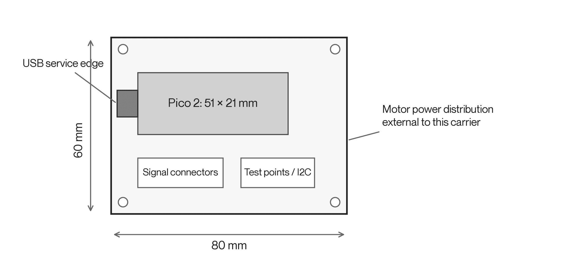
The first PCB is proposed as an 80 × 60 mm carrier for the controller, connectors, protection and measurement interfaces. A provisional 90 × 70 × 25 mm cassette allowance includes some assembly space, but has not yet demonstrated fit in the original enclosure. The rear power cover and front control panel need to be detailed alongside that board.
Actuator identification comes before purchasing. The imported CAD reference is labelled MG958 DIGI Servo; similarly sized catalogue servos are not automatically compatible with its horn, spline or mount. One measured motor station will settle more than another round of optimistic part substitutions.
PCB packaging proposal only. This is not a routed, manufactured or tested circuit board.
What is resolved, and what the bench must answer
The work so far connects a mechanical concept, a reproducible geometry model and an original product form. The CAD comparison provides a useful check on selected poses. The enclosure gives the device a clear interaction face and a dedicated power area without hiding the mechanism.
The next step is one complete motor station: confirm the actuator and horn, measure angle response and backlash, check current and temperature, and resolve joint engagement. Then come the full mechanism, limited motion, camera calibration, single-axis balance and two-axis path tracking. Manufacturing preparation follows those interfaces, with attention to bends, cover fit, tool access and repeatable assembly.
The software direction is equally concrete: log target and measured position, timing, saturation and active limits in a web experiment panel. AI-assisted analysis may later help compare runs or explain anomalies; it is a proposed analysis layer, not the real-time control loop. The first convincing result will be a repeatable physical experiment with data that can be replayed.