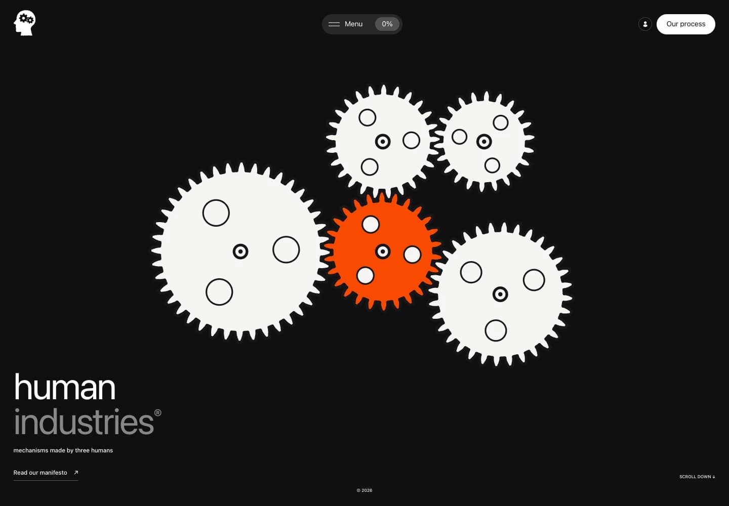
When I study a mechanism, I tend to follow how motion travels from one part to another. A gear turns, a link shifts, and a few simple connections produce a movement I did not expect. That curiosity was my starting point for the Human Industries identity and website.
Human Industries is a community that believes we can solve problems through mechanisms. I wanted visitors to get a feel for that approach by turning a mechanism, pausing to inspect its connections and trying an arrangement of their own. I designed the identity, mechanism library and Lab around those activities.
01 / IdentityHuman Industries.
I combined a human head and two gears in one mark.
02 / Colour
#10100F#F5F5F2#F94A00
03 / Behaviour
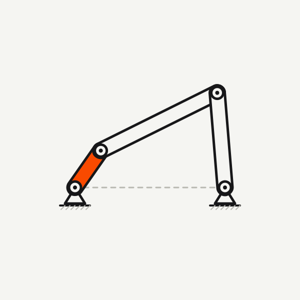
I included mechanism drawings in the identity.
How I built the mark
I placed two gears inside a human-head silhouette to bring the community's interest in people and mechanisms into one mark. I kept the outer shape simple and paid attention to whether the gears could still be distinguished at a small size.
I chose charcoal and off-white as the main colours, reserving orange for driving parts, focus states and interactions. That gave me a way to carry the relationship in the logo into the connections and controls on the page.
Taking the identity across surfaces
I needed the logo to work beyond the top of the homepage. At a large size, I wanted the gears to be visible in detail. At browser-icon size, I wanted to retain the head silhouette. I focused on those changes in scale without adding more symbols around the mark.
I used light mechanism lines on dark backgrounds and light surfaces where technical drawings needed more detail. I kept orange selective: when it identifies a joint or driving part, I want the eye to start following the movement there.
I tried to write as I would when explaining a part at a workbench. I begin with what I am looking at, then explain how it works. In a technical document I can make that explanation denser; on the website I leave more room to try the movement.
I used this drawing to explore building together.
How I organised the website
I used the homepage to introduce what Human Industries is interested in. I built the mechanism library for closer study of a particular movement and the Lab for trying arrangements of parts. I wanted each page to support a different depth of exploration.
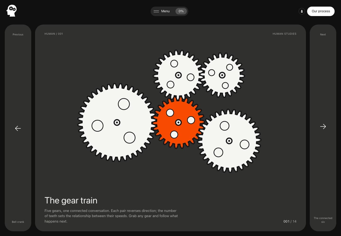
In the library, visitors can switch between mechanism studies. In the Lab, they can pause motion, add a part and undo changes. I worked with two-dimensional kinematics, focusing on making connections and motion transfer understandable.
Making mechanisms readable on screen
I did not expect a first-time visitor to know every technical detail. I built a route from the homepage to the library and into the editing surface, so someone could begin by watching a mechanism and look closer when a particular connection caught their attention.
I updated the address when the selected library study changed. That makes it easier to return to a mechanism or share a link to it. The selected movement can be reached directly.
In the drawings, I distinguished fixed parts, driving parts and the links transmitting motion. I used pivots and connection lines to explain how the pieces relate, with orange identifying the driving part. Those choices give the viewer a place to start following the movement.
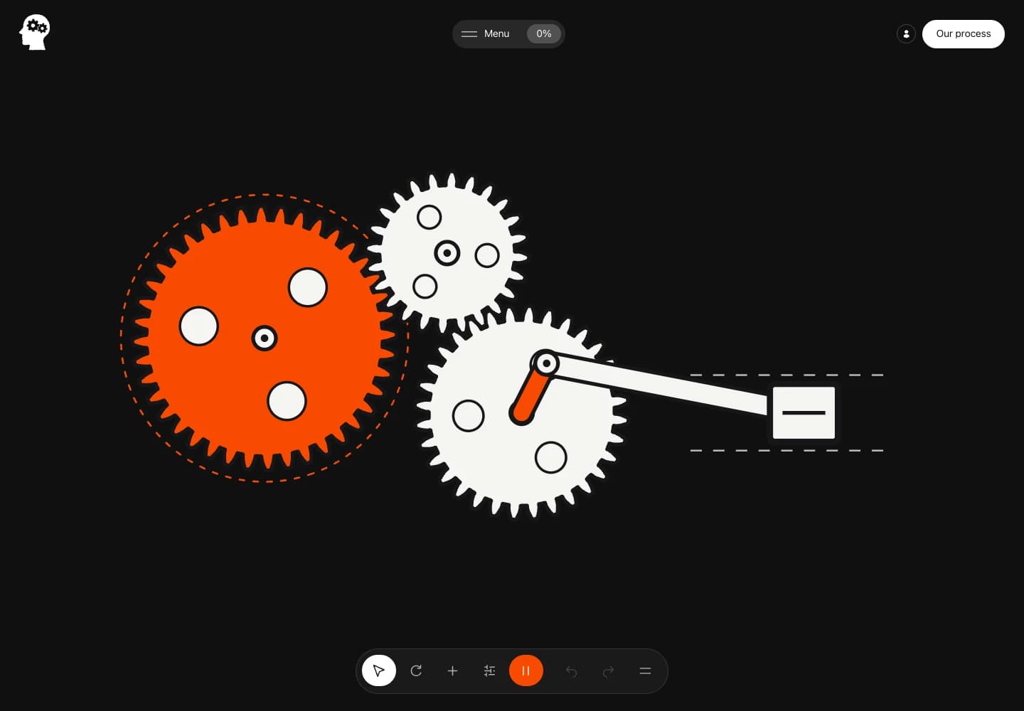
I brought the mechanism studies together in this library.The add, pause and undo controls I prepared for the Lab.
Trying arrangements in the Lab
I wanted to be able to reverse a change without losing the arrangement I had been exploring. Pausing should let me inspect a connection; adding a part should let me compare the result with the previous state. I placed the pause, add, undo and redo controls around that workflow.
When checking the Lab in the browser, I added a gear to an arrangement that started with three. Undo returned it to three; redo brought the fourth gear back. I also checked that the arrangement remained after a reload. I stored these experiments in the browser to reduce the need to start again on every visit.
Here I am most interested in seeing how a connection behaves. Moving a part and watching the rest of the arrangement respond helps me understand the mechanism. I address material and sizing decisions in the calculation and modelling work for the flywheel.
Developing the flywheel concepts
The engineering project I am working on with Human Industries is a stationary flywheel unit that stores energy in a rotating rotor. I am exploring a mechanical arrangement for short-duration grid-frequency support.
For initial sizing, I started with targets of 100 kW in either direction at the electrical interface and at least 25 kWh of usable mechanical energy. I developed rotor alternatives around those targets. I am examining a composite rim, laminated steel plates and a variable-inertia approach alongside their material, assembly, bearing and containment requirements.
Energy and the operating range
I separated stored energy from interface power at the start of sizing. For short-duration frequency support, both the amount stored and the rate of transfer affect the design. I am also considering standby losses and operating limits in that calculation.
I calculate usable mechanical energy from the difference between the rotor's maximum and minimum operating speeds: E = ½ I (ωmax² − ωmin²). That means I need to consider inertia and speed range together. Different mass and geometry choices can approach the same energy target.
Dividing 25 kWh by 100 kW gives me 15 minutes in an ideal, loss-free calculation. I treat motor/generator losses separately. For containment, I consider the total kinetic energy at maximum speed. Keeping that quantity separate from the usable energy difference is one of the things I pay attention to when comparing concepts.
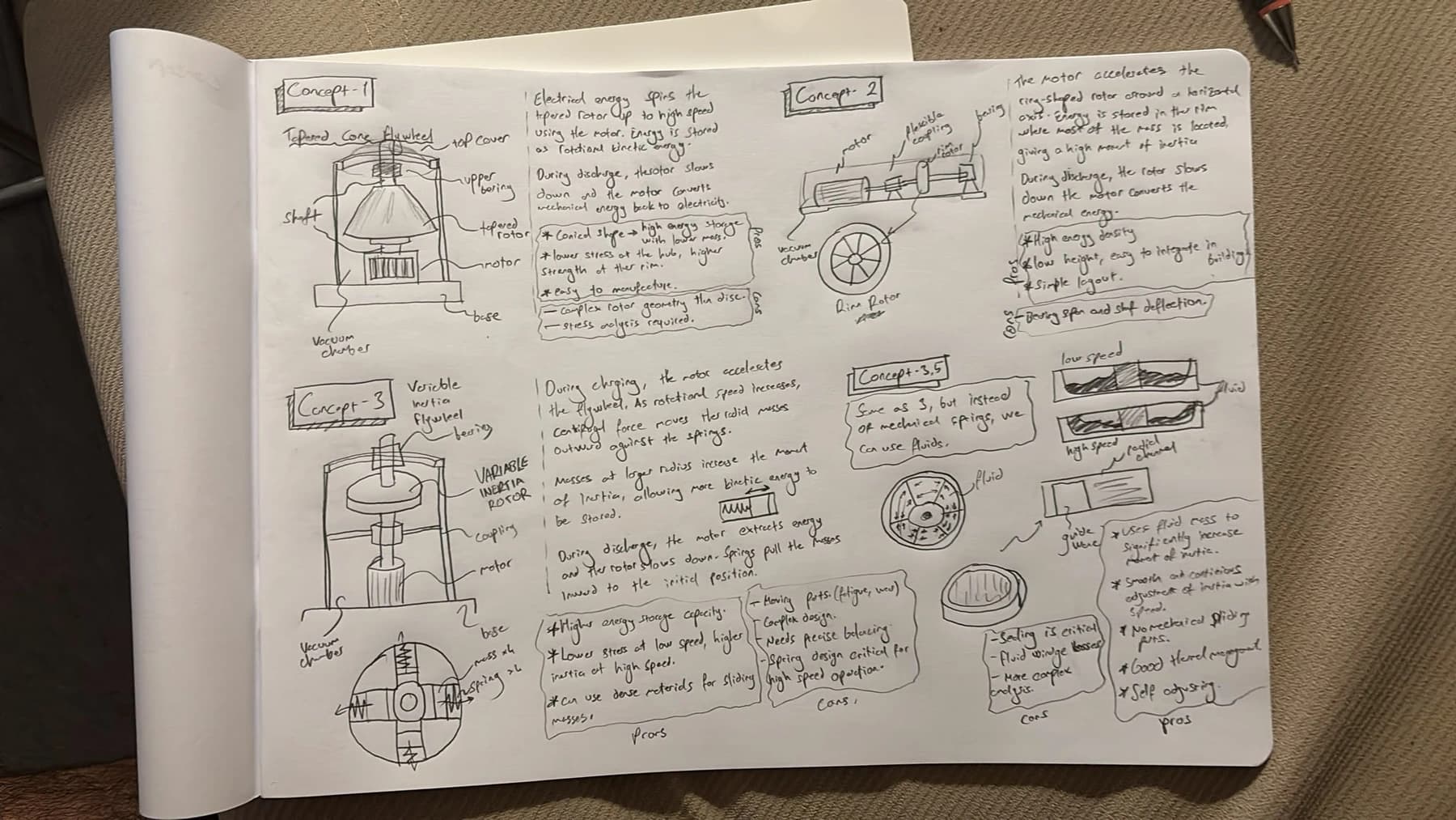
I used this drawing to explain storing energy in rotation.The first concept sketches I prepared for the flywheel.
The rotor alternatives I am working on
CarbonSpin: a composite rim
For CarbonSpin, I explored a composite rotor carrying its storage mass in the outer rim. I considered the carbon/epoxy outer rim, inner rim, flexible aluminium hubs and motor/generator in the same section, including the bearing arrangement.
I am particularly interested in the hub-to-rim connection. Manufacturing the composite part, its high-speed behaviour and vacuum requirements also affect the layout. I am comparing the material's effects on mass and losses alongside the sizing work.
StackWheel: laminated steel plates
For StackWheel, I explored a rotor assembled from stacked steel plates. Changing the number of plates lets me consider different arrangements of the storage mass. I drew the fasteners, end flanges and bearing cartridges as parts of that assembly.
My questions here centre on the joints. I am examining stresses around the holes, how the plates are held together and how they could be taken apart for maintenance. I am considering rotor integrity and containment alongside the plate arrangement.
Variable inertia
In another concept, I explored masses moving radially to change the moment of inertia. I considered springs and moving masses within the same arrangement. That led me to look at guidance, balance throughout the movement and the path each part would follow.
Drawing these options side by side helps me see which calculations each one needs. A material choice changes more than rotor mass; I also need to revisit assembly, bearings and containment.
How I planned the work
I divided the flywheel into subsystems to keep track of which decisions affect which parts. I prepared the partition tree for that purpose and placed research, concept development, detailed design and reporting into the semester timetable.
I have shown my 17 October plan here in two views that can be read directly on the site. The tree's branches can be expanded and collapsed; the Gantt displays work periods alongside due dates. I focused the mechanical study on the rotor, bearings and containment, defining its relationships with the electrical and control systems through interface values.
The system tree and timetable
I placed the rotor, bearings, motor/generator, housing and monitoring/interface components on separate branches. That helps me find the relevant part when considering a design decision. If I change the rotor arrangement, I can return to bearings and containment through the same tree.
I distributed 21 tasks across 13 weeks in the Gantt. I use it to follow the sequence from research and concept generation through detailed design and reporting. I distinguished work periods with light bands and due dates with blue cells, keeping the task names and T/I/M role codes in the English used in my plan.
Looking at the tree and timetable together helps me consider how a decision that grows in scope affects the schedule. I use both views to keep the calculations tied to rotor selection within the same period of work.
HUMAN INDUSTRIES / ME482 / FALL 2026
Design partition tree
I use this system tree and timetable to organise my mechanical design work.
Flywheel Energy Storage Unit (100 kW / 25 kWh)
Rotor assembly, expand or collapse components
Rim (energy storage mass)
Hub
Shaft
Bearing system, expand or collapse components
Upper & lower bearings
Axial / lift bearing
Backup (touchdown) bearings
Motor / generator, expand or collapse components
Stator
Rotor (magnets)
Cooling
Housing & containment, expand or collapse components
Vacuum chamber
Containment ring
Vacuum pump & seals
Mounting / base
Monitoring & interface, expand or collapse components
Speed, vibration & temp. sensing
Emergency braking
Power interface values
I organised my work around the mechanical subsystems and defined their relationships with electrical and control systems through interface values. I kept the technical labels in English.
My project plan, 17 October 2026 / p. 1 — Design partition tree
HUMAN INDUSTRIES / ME482 / FALL 2026
Project timetable
I use this system tree and timetable to organise my mechanical design work.
Planned workDue dateT = Team / I = Individual / M = Manager
Project timetable
Task / deliverable
Who
W1
W2
W3
W4
W5
W6
W7
W8
W9
W10
W11
W12
W13
Team formation
I
First team memo and preferred topic list
T
Project topic assignment
M
Need and problem statements
T
Scope and objectives
T
Patents and standards
I
Literature survey (journal articles)
I
Planned work, week 2
Design partition and timetable
T
Concept generation
I
Planned work, week 3
Planned work, week 4
Concept selection
T
Mid-term presentation
T
Planned work, week 5
Detailed design: rotor, hub and shaft
T
Planned work, week 7
Planned work, week 8
Planned work, week 9
Detailed design: bearings and motor/generator
T
Planned work, week 7
Planned work, week 8
Planned work, week 9
Detailed design: housing and containment
T
Planned work, week 8
Planned work, week 9
Risk analysis
T
Cost analysis
T
3D CAD model and drawings
T
Planned work, week 9
Planned work, week 10
Planned work, week 11
Report and final presentation work
T
Planned work, week 10
Planned work, week 11
Planned work, week 12
Planned work, week 13
Midterm exam
I
Final presentation
T
Final report submission
T
I kept the task names in English, separated work periods from due dates and used T/I/M codes for role groups.
My project plan, 17 October 2026 / p. 2 — Project timetable
What I am working on now
I am continuing to develop the flywheel concepts. My current focus is sizing the speed range, moment of inertia and usable energy together. As I establish those values, I am comparing bearing, loss and containment choices within the same arrangement.
Next, I want to develop the calculations and model for the selected rotor approach in more detail. I keep the concept sketches open throughout that process so I can see how a calculation changes the drawing and reconsider the arrangement.